Setting up Arduino for ESP32
Before you start controlling the world around you, you’ll need to set up the software to program your Sensything.
Step 1: Download and Install the IDE
The Arduino Software (IDE) allows you to write programs and upload them to your Sensything. Now you require arduino Desktop IDE.You can download the latest version for windows, linux and Mac OS using the below link .
https://www.arduino.cc/en/Main/Software#download
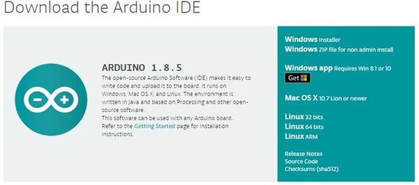
Note: Once you have downloaded, install the IDE and ensure that you enable most (if not all) of the options, including the drivers.
Step 2: Get the Sensything COM Port Number
Next you will need to connect the Sensything board to a system. This is done via a USB connection. When the Sensything is connected, the operating system should recognize the board as a generic COM port. The easiest way to do this is to type Device manager into Windows Search and select Device Manager when it shows.
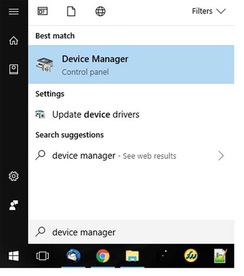
In the Device Manager window, look for a device under Ports (COM & LPT) and chances are the Arduino will be the only device on the list.
Step 3: Configure the IDE
Now that we have determined the COM port that the Arduino is on, its time to load the Arduino IDE and configure it to use the same device and port.You have to install the esp32 platform in the Arduino IDE to find esp32 board in board manager.For installing esp32 platform follow up th link:
https://github.com/espressif/arduino-esp32/blob/master/docs/arduino-ide/boards_manager.md.
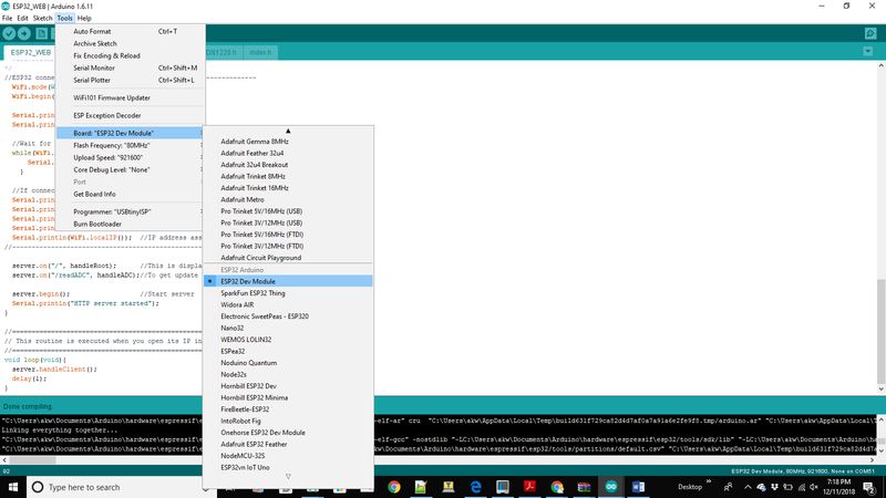
You can start by loading the IDE. When it is loaded, navigate to Tools > Board > Esp32 dev module.
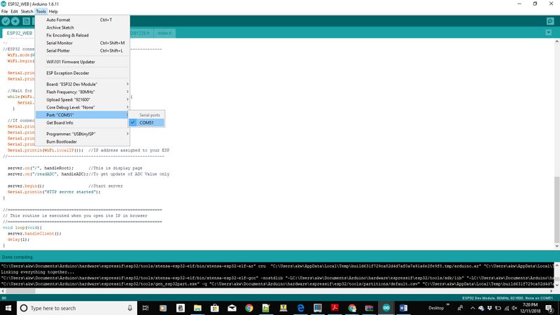
Next you must tell the IDE which COM port the Sensything is on. To do this, navigate to Tools > Port > COM51. Obviously, if your Sensything is on a different port, select that port instead.
Step 4: Writing my first code to Sensything
A header file is generally used to define all the functions, variables and constants contained in any function library. Define the pin number of ads1220 Chip select and DRDY.
#include "Protocentral_ADS1220.h"
#define ADS1220_CS_PIN    4
#define ADS1220_DRDY_PIN  34
Initialize the onboard ADS1220 ADC with begin
void setup()
{
  Serial.begin(9600);

  pc_ads1220.begin(ADS1220_CS_PIN,ADS1220_DRDY_PIN);

  pc_ads1220.set_data_rate(DR_330SPS);
  pc_ads1220.set_pga_gain(PGA_GAIN_1);
  pc_ads1220.set_conv_mode_single_shot(); //Set Single shot mode
 }
In the loop function below we get the ADC data for Channel 0, the same logic can be applied to read channel 1, channel 2 and channel 3.
void loop()
{
  adc_data=pc_ads1220.Read_SingleShot_SingleEnded_WaitForData(MUX_SE_CH0);
  Serial.print("\n\nCh1 (mV): ");
  Serial.print(convertToMilliV(adc_data));
  delay(100);
}
Converting the adc data into millivolt
float convertToMilliV(int32_t i32data)
{
    return (float)((i32data*VFSR*1000)/FULL_SCALE);
}
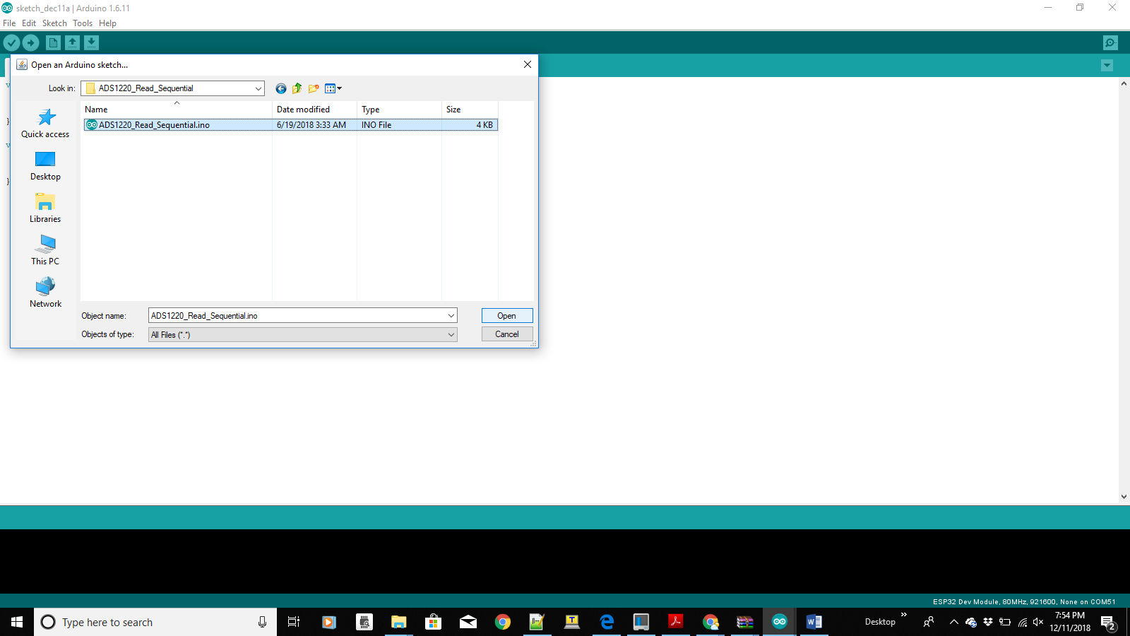
Getting the above code is as easy as installing the Arduino library https://github.com/Protocentral/Protocentral_ADS1220 and loading the simple ads1220 data acquisition example from the Arduino IDE’s menu:File > Open > Protocentral_ADS1220.
Step 5: Compiling and Uploading
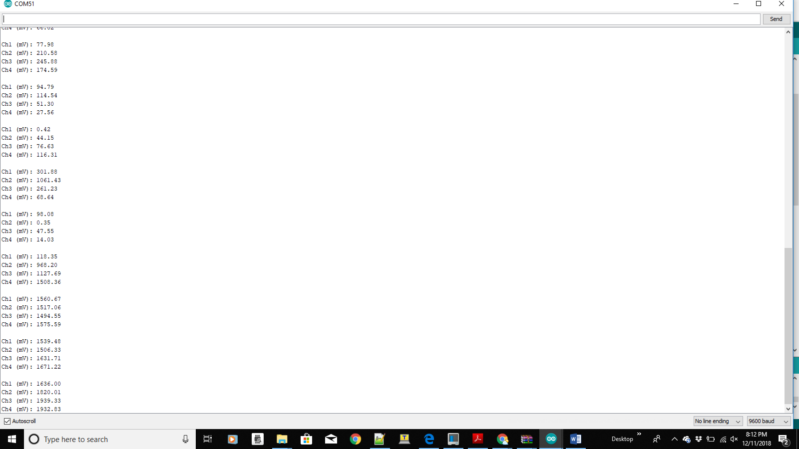
Compile the code and check for compilation without error and upload the code to Sensything so as to print the 4-channel analog readings in the Serial Monitor.
Its time to get started with some sensors to get the Real time output. We have showcased this in the following experiments with both Analog and Qwiic sensors.